About Goodies
TABLE OF CONTENTS
SYSTEM REQUIREMENTS
System requirements are the same as for ArchiCAD 19.
For more details, see "ArchiCAD 19 Getting Started" available from the ArchiCAD Help menu.
INSTALLING
Start this installer and follow the instructions. The add-on will be automatically loaded the next time you start ArchiCAD.
UNINSTALLING
Important: Do not remove the Java Runtime Environment before uninstalling Goodies.
Windows:
Go to the Windows "Control Panel" and select "Programs and Features" to remove all Goodies components from your computer.
You can also browse to your ArchiCAD 19 folder and execute the uninstaller in the Uninstall.GDS subfolder.
Mac OS X:
Browse to your ArchiCAD 19 folder and execute the uninstaller in the Uninstall.GDS subfolder.
This will start the uninstaller, which will remove all Goodies components from your computer.
INTRODUCTION - 3D Studio
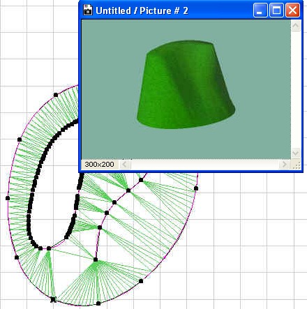
This ArchiCAD Add-On can convert 3D Studio (.3ds) files to ArchiCAD GDL objects. The conversion process can be customized by the user.
To convert a 3DS object:
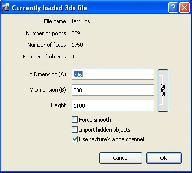
- Select the 3ds file with the Convert 3DS to GDL object command from the File/File Special/Import 3D Studio Files>>3DS Converter menu.
- The add-on displays information about the original 3DS file (number of points, polygons and object count). You can modify the object sizes (X dimension(A), Y dimension(B) and height).
- Force smooth option: The add-on tries smoothing all object surfaces.
- Import hidden objects: Hidden objects will also be imported from the file.
- Use texture’s alpha channel: The transparency information will be imported from the 3D Studio file, if the related TGA/TIFF textures contain alpha channel information.
- Click OK.
- The add-on checks whether the 3DS file contains texture links. If the defined texture file does not exist next to the 3DS file, the program asks the user to specify its location.
- During the conversion, the add-on copies all textures to the given destination folder alongside the converted GSM object.
- The add-on creates the new library part. The name will be generated from the original .3ds file name (without the.3ds extension). At the end of the conversion, a message is shown about the created .gsm file path.
Note:
Input data: a .3ds file (3DS Studio file), and occasionally jpg or other texture files. Texture file formats must be one of the picture formats that ArchiCAD supports. Currently these are BMP, GIF, TIFF, TGA, JPG, PICT.
Output data: a .gsm file, and occasionally some texture files (jpg, gif, pict, ...) registered to ArchiCAD Library Part manager.
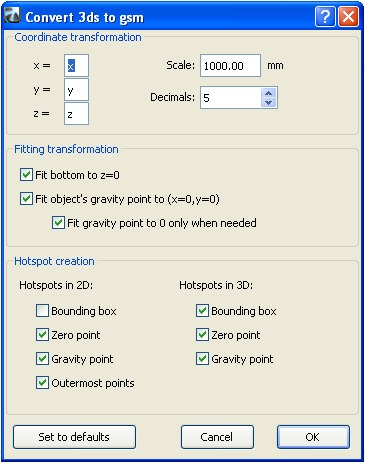
Conversion Options
The conversion process is customizable with the Options.. command from the File/File Special/Import 3D Studio Files menu.
Coordinate transformation:
The user can assign the correct x,y or z instead of the original (x=x, y=y, z=z) assignment. There can be a '-'-sign before x, y or z. For example, when 3ds file is converted from Lightwave, the recommended assignment is: x=x, y=z, z=y.
Scale: Sets how many millimeters correspond to a unit in the 3ds file.
Decimals: Specifies the precision of the converted object’s size.
Fitting transformation:
Fit bottom to z=0: fit the object's bottom to z=0.
Fit object’s gravity point to (x=0, y=0): fit the object's gravity point to (x=0, y=0) in the top view.
Fit gravity point to 0 only when needed: this means that "fit gravity point to x=0, y=0" works only when the object in the 2D top view doesn't contain the (x=0, y=0) point (the 2D origin).
Hotspot creation:
Hotspots in 2D:
Bounding box: Automatic ArchiCAD bounding box (this will also occur when no hotspots assigned for 2D)
Zero point: x=0, y=0
Outermost point: Top left, bottom left, top right, etc.... max. 8 hotspot points from among the object's points
Gravity point: The object's gravity point
Note: The selected option results in hotspots in 3D too!
Hotspots in 3D:
Bounding box: Maximum of 6 of the outermost points. Each of these hotspot points is a point on the object.
Zero point: x=0, y=0, z=0
Gravity point: The object's gravity point
Destination Folder
The location of the converted GDL objects is configurable with the Set Destination Folder command from the File/File Special/Import 3D Studio Files menu.
INTRODUCTION - Accessories
With the help of this ArchiCAD Add-On you can supplement the roof, slab and wall elements with special objects.
First, select an existing building element (wall, roof or slab) on the Floor Plan, and then choose the appropriate command from the Design > Design Extras > Accessories hierarchical menu.
The Choose Accessory Object dialog box prompts you to select an Accessory object. Set the object's parameters on the Parameters and Custom Settings panels. Other parameters (for example, the slope of a roof) will be set automatically when placing the object, based on the settings of the associated building element. Click OK in the Accessory Object dialog box, then click on the Floor Plan to place the Accessory Object.
After placing it, you can select it and modify its parameters at any time.
- You can also place an Accessory Object without selecting a corresponding building element.
- Select an Accessory Object from the Choose Accessory Object dialog box and set its parameters.
Draw a polyline on the Floor Plan. The selected Accessory Object will be placed with the polyline geometry method.
Note: Accessory Objects placed on their own are not associated to any element; that is, they have separate attributes and can be moved and edited on their own.
Note: You cannot associate an accessory to an element which is not of its type; for example, a roof accessory placed atop a slab will be an independent object.
The Accessories commands update all parameter values of the placed objects appropriately:
- When you delete an element, associated Accessory Objects will also be deleted.
- When you modify an element, all parameter values will be updated on the fly (wall geometry may change when stretching connecting walls).
To simplify the procedure, you can save variations of the Accessory Objects as Favorites. You can also create customized variations by opening an object and saving a copy with a different name, and then modifying the custom parameters and/or scripts.
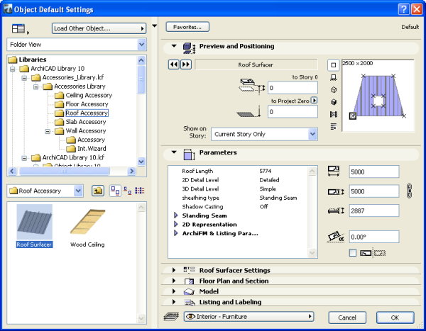
Roof Accessories
The Roof Accessories command allows you to place the Roof Surfacer or Wood Ceiling object.
Roof Surfacer can model roof sheathing with metal sheets or tiling based on the setting in Roof Surfacer Settings Panel. (The Sheathing Type can also be selected in Parameters Panel.)
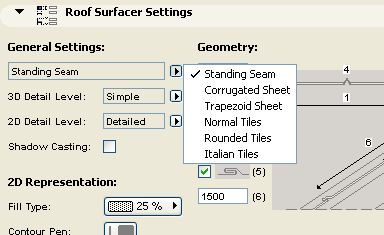
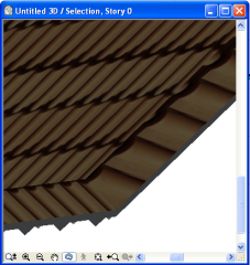
Note: The surfacing is done tile by tile, and can add considerable geometric detail (and, consequently, rendering time) to each roof plane. Curved surfaces are more demanding on the computer's resources than planar surfaces.
Slab Accessories
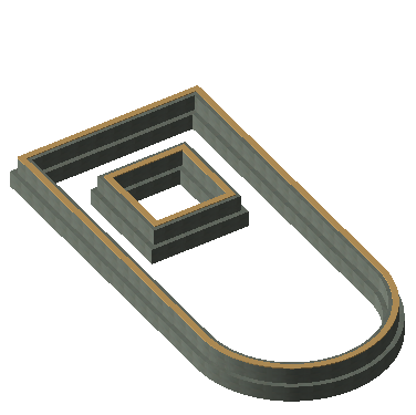
When choosing the Slab Accessories command, you can choose between two objects.
The Footing 1 object can model a concrete footing with stem wall and sill plate.
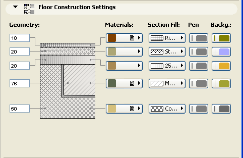
The Floor Construction object can model layered floors.
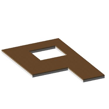
Use the Floor Construction Settings, Section and Model panels to achieve the desired effect.
Wall Accessories
With the Wall Accessories command, you can place a variety of objects adding details to your walls.
The Moldings and Panelings object model interior details on walls consisting of up to three selectable molding profiles, and optional paneling (wainscot and wall panels) between these moldings.
The object's custom parameters can be set in the Choose Wall Accessory Object dialog box, on either the Custom Settings or the Parameters panel. Parameters are grouped according to different criteria on the two panels.
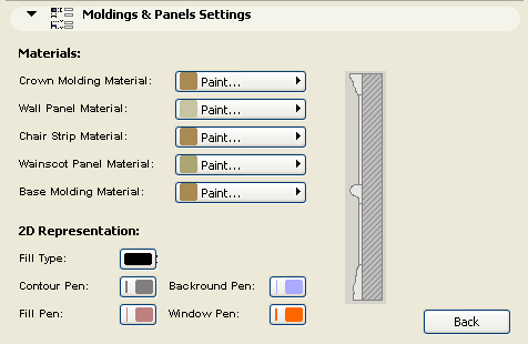
The Custom Settings panel has two pages:
- one for the General Settings, Geometry and Custom Angles
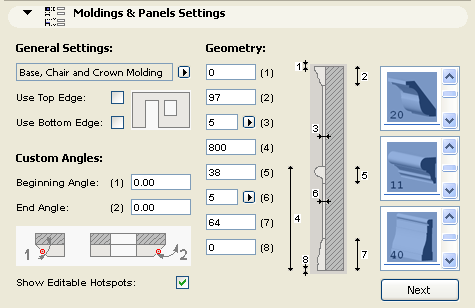
- and one for the Materials and 2D Representation
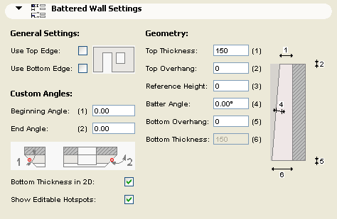
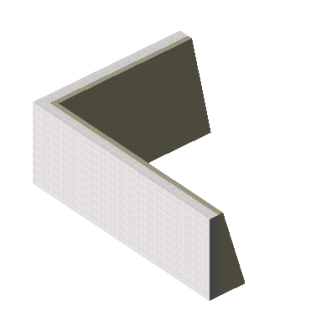
The Battered Wall object can model battered stone veneers and similar elements applied to a wall, and can have a different thickness at the bottom and the top. The object can extend beyond or end short of the bottom and the top of the wall by a specified distance.
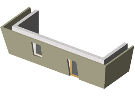
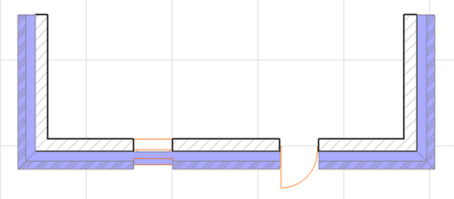
The Canted Wall object is an exact replication of the Wall it is derived from, except that it has a parametric tilting angle.
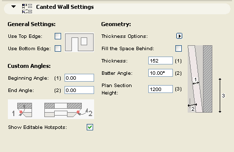
On the Floor Plan, the Canted Wall symbol shows the outside boundaries of the object, as well as the cross section at a given elevation (4 ft. by default).
The Wall Framing object can be used to represent stud framing within walls. It handles the properly added studs at right angle corners and incoming wall joints. At the windows and doors it adds double studs, cripples and jack studs as well as parametric headers. The top header plate is broken or extended to provide overlap at the joining walls.
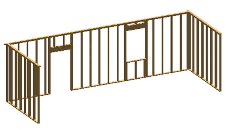
The parameter list for 2D Representation includes an on/off checkbox for Show Framing Elevation. Switching this parameter On enables you to edit the 3D geometry on the Floor Plan.
Restrictions: Openings for Doors and Windows will have horizontal edges perpendicular to the original wall plane. These objects have their property script set up to provide LUMBER PACK calculation where the individual pieces are listed with their nominal cross section sizes and their length is rounded up - if necessary - to the next inch. The list also gives an estimate on the overall board feet quantity.
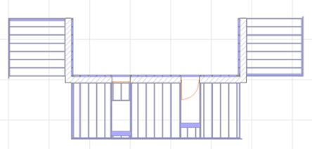
INTRODUCTION - Check Duplicates
This ArchiCAD Add-On can find, select or delete items sharing the same parameters (type, color, thickness, height, etc...) and occupying the same spot on the floor plan. Unwanted doubles are typically created by either accidentally double-clicking at the same mouse position or by copying and pasting items several times to the same location.
The Add-On will add two new command to ArchiCAD: Select Duplicates and Delete Duplicates
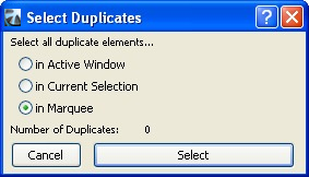
Select Duplicates
The Select... command will select and highlight all duplicated elements in the active window. If you placed a marquee in the window, or you have selected elements before evoking the command, then you can limit the range of the command to the marquee area or the selected elements. Only duplicates will be selected, the original item will not be affected.
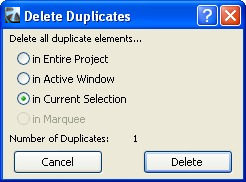
Delete Duplicates
With the Delete... command it is possible to delete duplicate elements over the entire project (all stories and sections). You can also limit the range of the command to the active window, or - if you have selected elements before evoking the command - to the current selection. Clicking the Delete button will delete duplicates, but will leave the original element intact.
Remarks:
- The Select Duplicates command only works on the active story or section.
- The Delete Duplicates command works on all stories.
- The Select/Delete Duplicates Add-On doesn't work for Section/Elevation lines and Cameras.
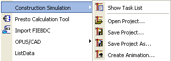
INTRODUCTION - Construction Simulation
The commands of the Construction Simulation hierarchical menu allow you to simulate the construction process with ArchiCAD's 3D model by associating construction elements to a task list. This list can be created within ArchiCAD or (in Windows only) imported from a Microsoft Project database.
Note: The Construction Simulation menu is only available when the Floor Plan Worksheet is the active Window.
Only one Construction Simulation project (task list) can be linked to an ArchiCAD Project. Opening a Construction Simulation Project with another ArchiCAD Project will create unresolved references.
The menu's commands are:
- Show/Hide Task List: opens the Construction Simulation dialog box, listing all the defined tasks with their status. Tasks can be defined directly in this dialog box or imported from a Microsoft Project database.
- Open Project: allows you to import a Microsoft Project database.
- Save Project: saves the task list in a database format.
- Save Project as: saves the task list in a database format under a new name. Use this to avoid overwriting the original database.
- Create Animation: allows you to create an animation showing the progress of the construction process.
Go to ArchiCAD and choose the Document > Schedules and Lists > Construction Simulation > Open Project command. In the dialog that appears, select the file you just saved from MS Project. Click Open.
The Construction Simulation dialog box opens.
The dialog box includes the following fields: Tasks, Type, Progress, Start Date and Finish Date. Fields can be edited by double-clicking in them. Clicking on any header will sort the task list by that key.
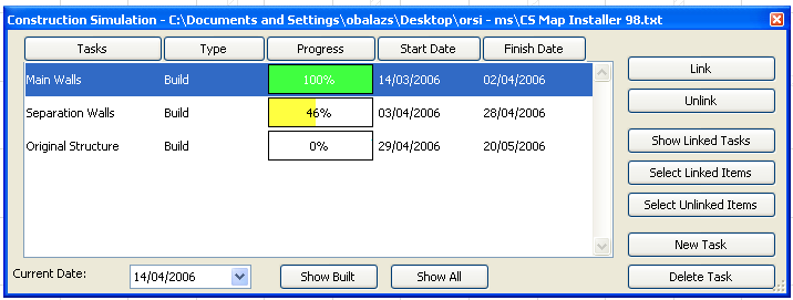
The Tasks, Start Date and Finish Date fields are imported from MS Project. You can either keep these or overwrite them, and you can manually enter new tasks.
The Progress field is automatically filled by ArchiCAD to conform to the Current Date defined at the bottom of the dialog box. Otherwise, this field is not editable.
Types are defined manually with a pop-up menu listing task types. There are five types of construction tasks:
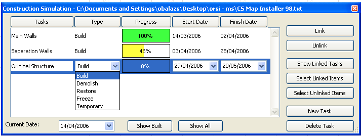
- Build: Elements do not exist when simulation starts. They are constructed during the task and then remain there.
- Demolish: Elements are present on the site when simulation starts. They are removed during the task.
- Restore: Elements are present both at the start and the end of the task. Work is performed on them during the task.
- Freeze: Elements are present both at the start and the end of the task, but no work is performed on them.
- Temporary: Elements are not present when simulation starts. They are constructed during the task and are removed at the end of the task.
When the task list is complete, you can start linking ArchiCAD elements to the items of the task list.
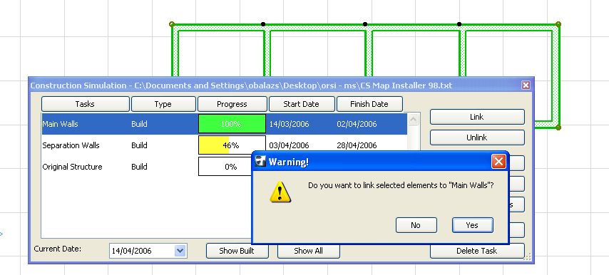
Go to the Floor Plan Window and select some elements. In the Construction Simulation dialog box, select the task that you wish to link the elements to and click the Link button on the right.
Note: Any element can be linked to as many as 10 tasks at the same time.
The buttons on the right-hand side of the Construction Simulation dialog box allow you to manage the task list.
- Link: assigns a task to selected Floor Plan elements.
- Unlink: deletes the link between the selected task and the Floor Plan elements it has been assigned to.
- Show Linked Tasks: highlights the names of the task(s) assigned to the element selected on the Floor Plan.
Note: If you select a highlighted task in the list, the button's name changes to Unmark Task.
- Select Linked Items: will select the elements on the Floor Plan to which the highlighted task is assigned.
- Select Unlinked Items: will select Plan all elements on the Floor that have not been linked to any task.
- New Task: allows you to add new tasks to the list.
- Delete Task: will remove the highlighted task from the list.
Once the task list is complete, you can simulate the construction process using the controls at the bottom of the Construction Simulation Window.

The Current Date field allows you to check the date or to choose another day to show the state of the building.
The Show Built button will show elements in their current state. It will also move all elements whose construction has not started yet on a hidden layer called "CS Hidden Layer". These elements will not appear in either ArchiCAD Window until you choose to show them again.
Clicking the Show All button will revert the display of all elements to their "normal" state. It will also move the elements hidden by the Show Built button back to their original layers.
Different construction states are displayed in different ways. ArchiCAD divides the linked elements into three categories according to the current date. This division is triggered when the Show Built button is clicked.
- Completed elements are displayed with their normal color (pen color on the Floor Plan, material in 3D).
- Started elements are displayed with different colors according to the task type. See section below for description of color changes.
- Elements whose construction has not started yet are moved to the "CS Hidden Layer" and are not displayed at all.
According to task types, the color changes are as follows:
- Build type elements are not visible before their task starts; they are displayed with pen number 251 on the Floor Plan and with the predefined "CS Build" material while the task is carried out and are displayed with their full original colors when completed.
- Demolish type elements are visible with their full original colors until the task starts; they are displayed with pen number 252 on the Floor Plan and with the predefined "CS Demolish" material while the task is carried out; and are not visible any more when the task is completed.
- Restoration type elements are visible with their full original colors before the task starts and again when the task is completed. While the task is carried out, they are displayed with pen number 253 and with the predefined "CS Restoration" material.
- Freeze type elements are visible with their full original colors before the tasks starts and again when the task is completed. While the task is carried out, they are displayed with pen number 254 and with the predefined "CS Freeze" material.
- Temporary elements are not visible either before the task begins or when it is completed. While the task is carried out, they are displayed with pen number 255 and with the predefined "CS Temporary" material.
Note: CS Build, CS Demolish, CS Restoration, CS Freeze and CS Temporary are predefined, transparent materials that have no texture or 3D hatching associated with them.
Choosing the command displays the Animation dialog box.
On top of the dialog box, you can define the starting and finishing date of the simulation.
In the middle section, you can define the interval in days. The number of frames field is grayed, as it uses the current setting of the Create Fly-Through command. In the bottom part, you can choose between using the current view or an existing camera path for creating the animation.
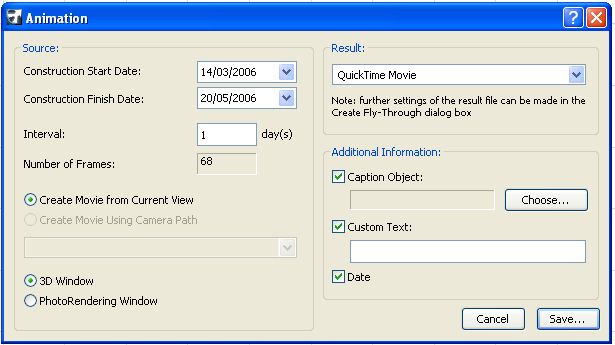
Note: If you choose the current view, check your settings in the Image > 3D Projection Settings dialog box and make sure that a perspective view is set up.
On the right, you can choose to save the movie in QuickTime Movie or AVI (Windows only) format and define additional information such as a caption and custom text. When you click Save, you can define the location of the animation file.
Export A Project From MS Project
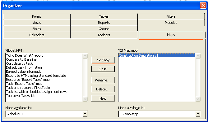
Before you can export a Project from Microsoft Project to ArchiCAD, first you need to open the CS Map.mpp file in MS Project.
Then go into the Tools Menu > Organizer > Maps Tab Page and copy the Construction Simulator v1 map from the right side into Global.MPT
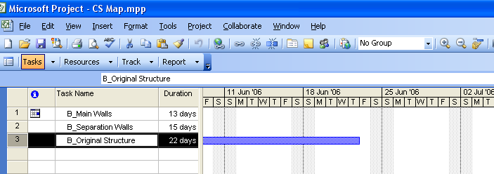
When creating the Task list in MS Project, you have to follow a strict naming convention - before the task names you need to use the following prepositons:
- B_taskname for build type tasks
- D_taskname for demolish type tasks
- R_taskname for restore type tasks
- F_taskname for freeze type tasks
- T_taskname for temporary type tasks
The date format must be MM/DD/YYYY format: e.g: 4/14/2015
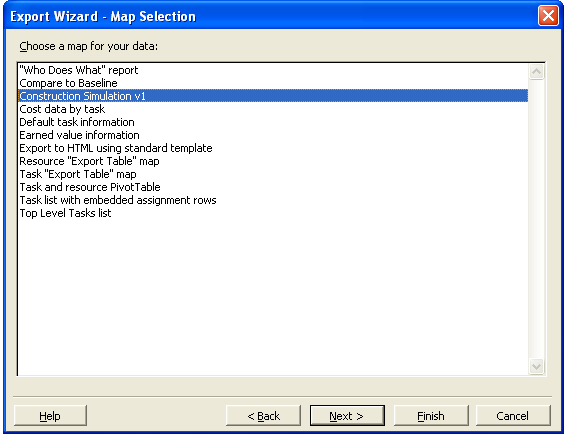
When saving the MS Project file, choose File > Save as. Select the text file format and click Save. In the appearing Export Mapping dialog, select the "Construction Simulation" format and click the Save button.
INTRODUCTION - Interior Wizard
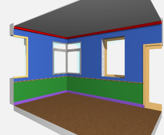
The Interior Wizard command enhances the modeling of 3D Zones by applying Accessory Objects to selected walls, ceilings and floors and creating interior finish elements. You can edit the shape and the material parameters of these elements using standard ArchiCAD tools as well as parametric functionality. The Interior Wizard recognizes wall openings and is updated if its associated zone is updated or changed. The Interior Wizard relies on the objects stored in the Accessories Library.
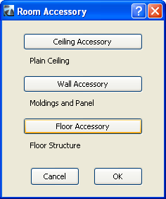
First select a 3D Zone on the Floor Plan. Choose Interior Wizard > Create Room Accessories from the Design > Design Extras menu. A dialog box prompts you to select among Accessory objects.
Press any of the three buttons (Ceiling Accessory, Wall Accessory, Floor Accessory) to bring up the Choose Accessory Object dialog box. Choose an object and make the appropriate settings. The principle is the same as for the Accessories commands.
When you have selected an object for one or more accessory type, the Interior Wizard dialog box changes to reflect your object selection.
Press OK to place the Accessory Object(s) on the surface of the 3D Zones. If the given room's Zone is changed or updated, use the Update Room Accessories command from the Interior Wizard menu to update the placed Accessory Objects.
INTRODUCTION - Intersections in Layer Combinations
With this Add-On you can assure that visible building elements do not interact with invisible building elements.
In ArchiCAD 8 and subsequent versions, intersection cleanup is linked to the Intersection Group Numbers assigned to layers. Elements which belong to layers having the same Intersection Group Number will intersect, regardless of layer visibility. Elements which belong to layers having different Intersection Group Number will not intersect. The Intersection Group Number of layers are stored with Layer Combination, so the same layer can have a different Intersection group Numbers in different Layer Combinations.
With this Add-On, you can automatically assign Group Number "1" to all visible layers and a Group Number "0" to all invisible layers registered in Layer Combinations.
Important:
- Any Intersection Group Numbers you have already set up in this project will be overwritten.
- Changing layers one by one may still result in visible elements without clean intersections.
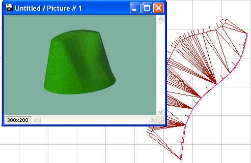
INTRODUCTION - Mesh To Roof
Irregular "free-form" shapes can be modeled using the mesh tool. These items can be converted to roofs with this Add-On.
The selected mesh object(s) can be transformed into grouped individual roof planes.
The individual roof planes can be deleted or edited further, their pitch can be modified, etc.
There are more editing options for the resulting surface patches than for the mesh object they originated from.
INTRODUCTION - Polycount
Polycount is an ArchiCAD 19 add-on that helps you control the number of 3D polygons in your ArchiCAD models. This tool can be used effectively if the project size or the limited physical memory of your computer makes the 3D model size a critical factor in your modeling decisions. Polycount can display the number of 3D polygons grouped by element types (walls, slabs doors, windows, objects etc.) and also their percentage compared to the complete model size. The add-on also allows you to change the 3D detail level of library parts in your projects.
After the successful installation, open the Polycount Palette from Window > Palettes. This palette is dockable and resizable just like any other ArchiCAD 19 palette.
Functions
1. Elements to be calculated
You can control the elements that should be calculated in the list on the first two tab pages of the Polycount palette:
- The Elements of Stories tab page provide option for calculating the polygons of a given story range
- The Selection only radio button on the Selection tab page allows you to calculate only the model elements within the actual selection
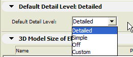
2. Default Detail Level
Polycount can change the level of detail (LOD) of certain library parts in the actual project. Library Parts can be adjusted individually on the 3D Model Size list or jointly from the Default Detail Level tab page. If you want to choose the Default Detail Level option the LOD of the required library parts have to be set to Default on the 3D model size tab page. Read more about it below.
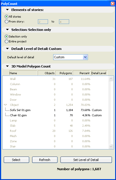
3. 3D Model Size of Elements
The list shows basic information about the actually opened model's 3D polygon size. Elements of the virtual building model are grouped by types (walls, slabs, doors, windows). Library parts can also be listed individually by clicking on the expand button near the element type name (only for doors, windows and objects).
- The first column (Name) shows the AC element types.
- The second one (Objects) indicates how many instances of the given element type are placed in the AC file
- Polygons show the number of 3D polygons generated in the 3D model from the given element type
- Polygon usage of elements can be viewed by Percent in the 4th column
- The Detail Level field is only applicable for library parts (doors, windows and objects). It has the following values: Detailed, Simple, Off, Custom, Default. See the description of the Set Level of Detail button for more details.
Model elements highlighted with the mouse in the 3D model size list can be selected on the floor plan with the Select button. These items can later be deleted or modified in order to reduce the number of polygons in the model.
The 3D Model Size list can be recalculated anytime with the Refresh button.
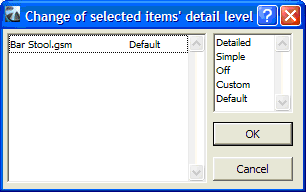
The Set Level of Detail button allows you to change the detail level of library parts selected on the list. Multiple library parts can be selected by holding down the shift key. Pushing the Set Level of Detail button will open a dialog where you can choose the required detail level for the selected objects. The following options are available: Detailed, Simple, Off, Custom, Default.
Most objects in the ArchiCAD library includes a 3D Detail Level parameter with options for Detailed, Simple and Off representations. The Set Level of Detail function allows you to toggle between these values. The Custom value is indicated if multiple instances of the same library parts are selected and their LOD value is different.
With the Default option active the LOD of selected objects can be set from the Default Detail Level tab page (see above). If you need to change the LOD of these elements again you don't have to select them on the list, you can modify them directly with the Default Detail Level option.
Limitations
- Objects belonging to hotlinked modules are marked on the list. The LOD of these elements can be set however this change will not have any effect on the library part and therefore the number of polygons will be calculated according to the elements' actual LOD parameter.
- The same limitation applies for objects in Teamwork projects that are not included in your workspace.
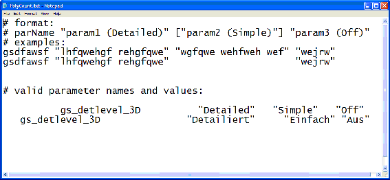
- Note that the LOD of a library part can only be changed if the necessary parameter is available on the object's parameter list. The variable name and the values of these parameters should be listed in the Polycount.txt file as shown below.
USEFUL LINKS
Disclaimer:
The software is provided to you "AS IS" and you acknowledge that it may contain errors. GRAPHISOFT disclaims any warranty or liability obligations of any kind.
©2015 GRAPHISOFT.
All rights reserved.
ArchiCAD is a registered trademark of GRAPHISOFT.
Other product and company names are trademarks of the respective holders.