With the help of this ArchiCAD Add-On you can supplement the roof, slab and wall elements with special objects.
Start this installer and follow the instructions. The add-on will be automatically loaded the next time you start ArchiCAD.
The new set of commands will appear in the "Design/Design Extras/Accessories" submenu by default.
First, select an existing building element (wall, roof or slab) on the Floor Plan, and then choose the appropriate command from the Design > Design Extras > Accessories hierarchical menu.
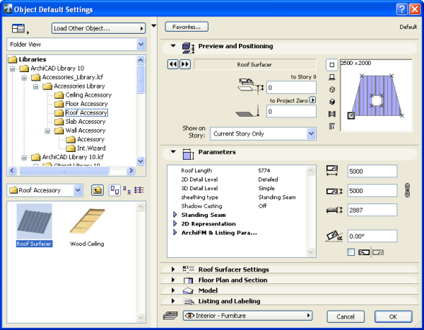
The Choose Accessory Object dialog box prompts you to select an Accessory object. Set the object's parameters on the Parameters and Custom Settings panels. Other parameters (for example, the slope of a roof) will be set automatically when placing the object, based on the settings of the associated building element. Click OK in the Accessory Object dialog box, then click on the Floor Plan to place the Accessory Object.
After placing it, you can select it and modify its parameters at any time.
The Accessories commands update all parameter values of the placed objects appropriately:
To simplify the procedure, you can save variations of the Accessory Objects as Favorites. You can also create customized variations by opening an object and saving a copy with a different name, and then modifying the custom parameters and/or scripts.
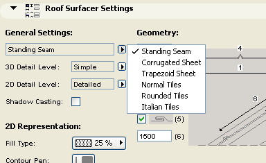
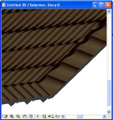
Note: The surfacing is done tile by tile, and can add considerable geometric detail (and, consequently, rendering time) to each roof plane. Curved surfaces are more demanding on the computer's resources than planar surfaces.
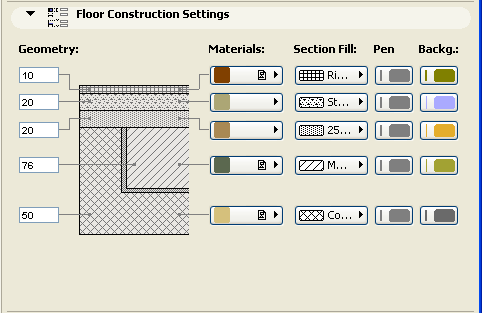
The Floor Construction object can model layered floors.
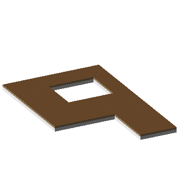
Use the Floor Construction Settings, Section and Model panels to achieve the desired effect.
With the Wall Accessories command, you can place a variety of objects adding details to your walls.
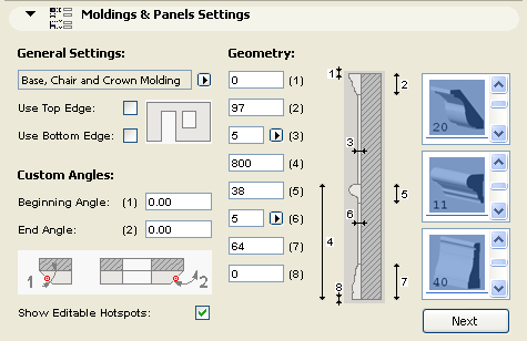
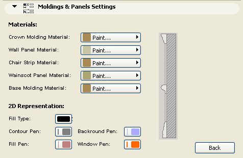
The Moldings and Panelings object model interior details on walls consisting of up to three selectable molding profiles, and optional paneling (wainscot and wall panels) between these moldings.
The object's custom parameters can be set in the Choose Wall Accessory Object dialog box, on either the Custom Settings or the Parameters panel. Parameters are grouped according to different criteria on the two panels.
The Custom Settings panel has two pages:
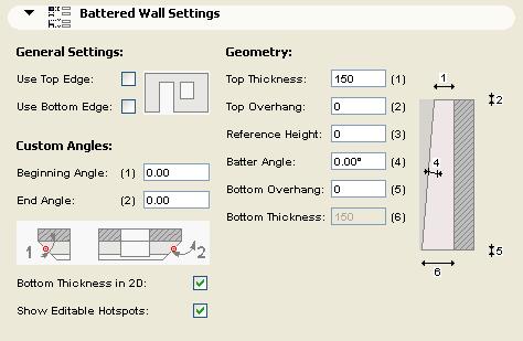
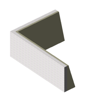
The Battered Wall object can model battered stone veneers and similar elements applied to a wall, and can have a different thickness at the bottom and the top. The object can extend beyond or end short of the bottom and the top of the wall by a specified distance.
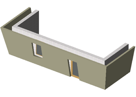
The Canted Wall object is an exact replication of the Wall it is derived from, except that it has a parametric tilting angle.
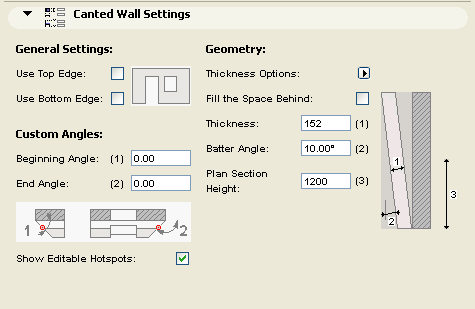
On the Floor Plan, the Canted Wall symbol shows the outside boundaries of the object, as well as the cross section at a given elevation (4 ft. by default).
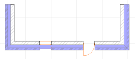
The Wall Framing object can be used to represent stud framing within walls. It handles the properly added studs at right angle corners and incoming wall joints. At the windows and doors it adds double studs, cripples and jack studs as well as parametric headers. The top header plate is broken or extended to provide overlap at the joining walls.
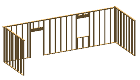
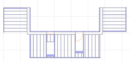
The parameter list for 2D Representation includes an on/off checkbox for Show Framing Elevation. Switching this parameter On enables you to edit the 3D geometry on the Floor Plan.
Restrictions: Openings for Doors and Windows will have horizontal edges perpendicular to the original wall plane. These objects have their property script set up to provide LUMBER PACK calculation where the individual pieces are listed with their nominal cross section sizes and their length is rounded up - if necessary - to the next inch. The list also gives an estimate on the overall board feet quantity.
The software is provided to you "AS IS" and you acknowledge that it may contain errors. GRAPHISOFT disclaims any warranty or liability obligations of any kind.